Controlling Plasma Temperature and Safety Factor with Gyrotrons Using Reinforcement Learning
In previous blog posts, we have shown how reinforcement learning can be used to control the shape of plasma in a tokamak. In a research environment, shape control is a basic requirement for any tokamak experiment: to study plasma, it helps to hold it in one place. The challenge we focus on is controlling plasma behavior in the constrained environment of fusion power plants (FPPs). In particular, we are interested in achieving ion temperatures of 10 keV or higher (for a D-T plasma), which requires an external heating system. Electron cyclotron resonant heating (ECRH) using gyrotrons is considered a convenient and FPP-relevant plasma heating mechanism. In the new ITER baseline, ECRH provides 49% to 56% of all external heating. [1]
Simulating heating sources means solving a model of wave-plasma or particle-plasma interaction, depending on the nature of the source. Base NSFsim [2] solves the MHD equations in the presence of energy source terms. Incorporating ECRH requires a separate physics model on top of the plasma evolution code. In this post, we extend NSFsim with a ray-tracing code, TRAVIS [3], and use reinforcement learning to control the plasma electron temperature (Te) and the safety factor (q), utilizing a digital twin of the DIII-D tokamak gyrotron system.
Gyrotrons on FPP
A gyrotron is a device that generates electromagnetic waves at frequencies of order 100 GHz and higher, which corresponds to the electron cyclotron frequency in fusion devices. This radiation is effectively absorbed by free electrons, increasing their energy and momentum, which, in a bulk plasma, corresponds to an increase in temperature and current. As far as state-of-the-art magnetic confinement fusion experiments are concerned, gyrotrons are a mature technology: there are several commercially available options which figure in devices such as ITER and STEP as part of the heating and current drive systems, and development is ongoing for the FPP-relevant frequency range of 200–300 GHz.
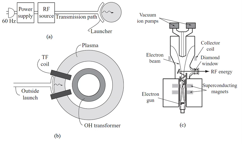
The interaction of electro-magnetic (EM) radiation with plasma is governed by the cold plasma dispersion relation and wave-particle resonance: the former tells us whether the wave will propagate through plasma or be reflected, the latter states that EM waves are effectively absorbed by plasma at frequencies close to the cyclotron frequency ωce = eB / me (56 GHz @ B=2 T) and its harmonics. In tokamak plasma, where the main component of the magnetic field is the external toroidal field Bₜ ~ B₀ / R, the following points summarize the physics of the electron cyclotron resonance heating [5]:
- The direction of the magnetic field fixes the choice of two polarizations at E ∥ Bt (ordinary mode/O-mode) and E ⊥ Bt (extraordinary mode/X-mode).
- Wave damping (i.e., absorption) is significantly stronger at the lowest harmonics of the cyclotron frequency.
- O-mode can access regions of plasma with sufficiently low density and is reflected off high-density regions.
- X-mode cannot access plasma when launched from a low-field region (i.e., outer wall of the tokamak) at the fundamental frequency; the second harmonic has the same properties as O-mode with twice the density limit.
From a control perspective, it is highly convenient that absorption is strongly dependent on the cyclotron frequency: combined with the radial dependency of the magnetic field, Bₜ ~ B₀ / R, power and current deposition are highly localized and can be rapidly adjusted, if necessary, using movable mirrors. Localization allows the use of gyrotrons not only as a heating and current drive (H&CD) source, but also as a tool to break up instabilities, such as the tearing mode, which is also localized around rational q-surfaces, before they can grow to disrupt the plasma. From an engineering standpoint, the small wavelength of ECRH radiation enables the usage of waveguides to connect a relatively compact launch port to the actual gyrotron, which can be moved away from the vacuum vessel. This is a significant advantage over either ion cyclotron heating (ICRH) with its large in-vessel antenna or neutral beam injection, where the entire system is positioned directly alongside the machine. Finally, from a simulation point of view, the propagation and absorption of ECRH waves can be adequately modelled using relatively simple ray-tracing codes. In the ICRH system, due to the long wavelength, the entire vacuum vessel acts as the resonant cavity, which requires solving a partial differential equation. In summary, ECRH is a practical way to heat and drive current in plasma.
As a side note, while electrons absorb ECRH radiation, it is ions that must be heated to fusion temperatures for fusion reactions to occur. The condition for ECRH to be effective in catalyzing fusion is for the electron-ion momentum exchange time to be significantly lower than the energy confinement time. This is satisfied in FPPs, but not in the present experimental devices, where gyrotrons are typically used to heat electrons, suppress instabilities, and drive plasma current.
Simulating gyrotrons and ECRH with NSFSim
To simulate EC heating and current drive, we start from a plasma equilibrium computed by NSFSim. In turn, each gyrotron is connected to a launch port, with a mirror determining the geometry of the actual EM wave. Since the wavelength at which the gyrotrons operate is much lower than the dimensions of the tokamak vessel, it is fair to model every beam as a collection of rays and use simple geometrical optics in conjunction with the MHD equilibrium to calculate energy absorption and current drive profiles.
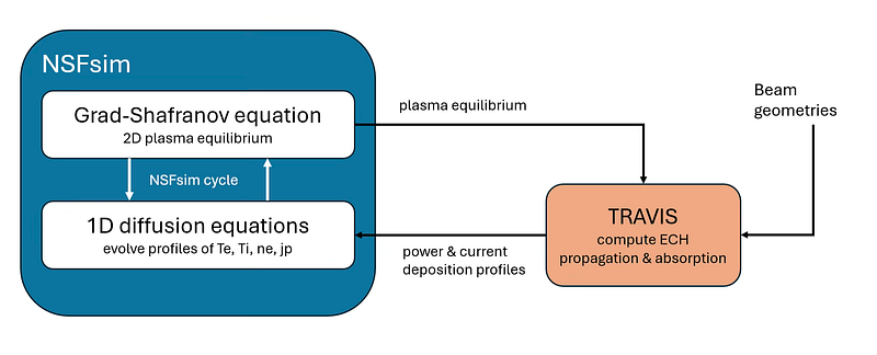
The TRAVIS code allowed us to do exactly that. In collaboration with the developers at the Max-Planck Institute for Plasma Physics, we have coupled TRAVIS to NSFSim, obtaining an integrated model of plasma evolution with accurately simulated electron heating and current drive. The end user, e.g., a machine learning or control engineer, works with a plant (a tokamak) equipped with gyrotron controls, with the specifics of the simulation hidden under the hood unless one wishes to tinker with the numerical parameters. When using reinforcement learning, the numerical performance of the plant model is essential; we have found a sweet spot that minimizes numerical error in TRAVIS while keeping its execution time on par with the rest of the plasma evolution code.
The final step is to incorporate the mechanical constraints of the actual tokamak into the model. On DIII-D, there are five different constraints:
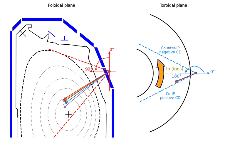
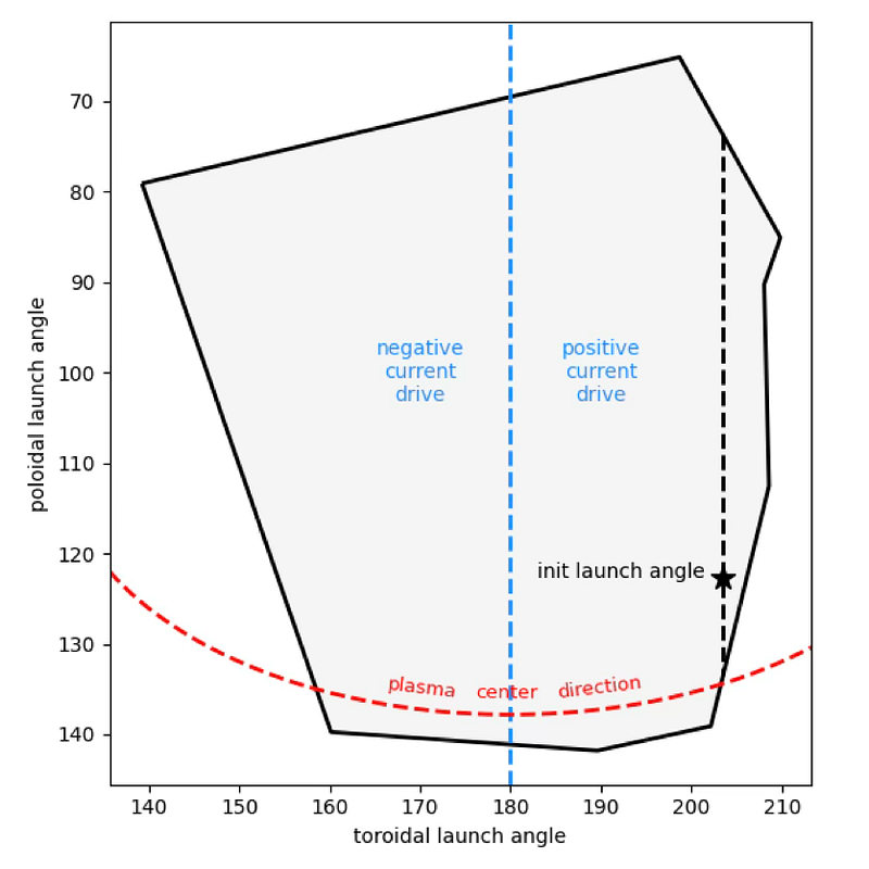
- The mirrors allow changing the beam launch angle in one direction (poloidal) in-shot.
- The mirrors rotate at a finite speed.
- There are limits on the beam launch angle due to the shape of the port.
- The duty cycle (0–100% power) is shared between all active gyrotrons.
- The port protection system shuts off the gyrotrons if the plasma density exceeds the wave propagation limit to prevent the beam from being reflected into the port.
We have included all constraints in the model except the last, since the requisite density limit is much higher than the plasma we are working on. The plant model is now ready to serve as the environment in reinforcement learning.
Results: Plasma profile control with reinforcement learning
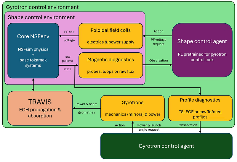
Setting up the hierarchical environment
The starting point for reinforcement learning is the environment, i.e., the plant model. Using our shape control environment, we train an agent to keep the plasma at a fixed position. On top of that environment, we implement a wrapper layer that prepares the observation for the profile control task, implements the mechanical constraints, and calls TRAVIS to convert control inputs into NSFSim source terms. This configuration allows us to train the two agents independently, whether using reinforcement learning or otherwise.
Problem formulation for reinforcement learning
The agent controls the launch angles for each of the 6 gyrotrons and the shared duty cycle, with a total of 3.2 MW of available ECRH power. Observations consist of the electron temperature and density profiles obtained from the simulator state, plus the time derivative of Te for the critic. To account for the effects of fueling/gas puffing, which is not modeled, bulk density is randomized within 10% of a reference value at each point in the episode. This roughly corresponds to the typical observable short-term density variations in reference experiments.
The flat Te profile maximizes effective fusion volume for a given energy input, and there is a simple steady-state solution: by applying all heating at ρ = ρlim, the temperature within that radius will equalize as time tends to infinity, at a rate dependent on the heat conduction out of the plasma volume. For this reason, the target Te profile is defined to be flat: Te (ρ) = Te, target in the region defined by the normalized toroidal flux 0 < ρ < ρlim.
We use the MAE = E [|Te (ρ) - Te, target|] (0 < ρ < ρlim) error metric and a logistic reward that ranges from 0 to 100% each step, depending on the error.
The control task is most interesting in the transition regime between two different steady states. We start from a state that was reconstructed from an actual experiment on DIII-D and evolve to a different steady state (conditional on NSFsim’s transport model) in 1 second-long episodes; for this episode length, we have observed that roughly the first 50% is transitory and the last half of the episode is steady-state, which allows us to evaluate both the dynamic and static performance of the controller.
Architecture and time slicing
We use the same neural network architecture as in the shape control task — a Multi-Layer Perceptron with a single hidden layer, 256 neurons wide — and the same reinforcement learning algorithm, Soft Actor-Critic.
The timescale of heat diffusion is slower than that required for shape control. We found that a step size of 20 ms is appropriate for temperature control. This also reduces the numerical load.
Sidenote: relevant diagnostics
Electron temperature and density profiles can be measured with diagnostics such as electron cyclotron emission (ECE) and Thomson scattering (TS). We are confident that, after establishing the basic capability for profile control with gyrotrons, we can move beyond using raw profiles to synthetic diagnostics without significant loss of control performance, if the diagnostics provide sufficient resolution and full coverage of plasma volume, as is the case on DIII-D.
Training with TRAVIS — temperature control
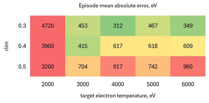
The initial state we use corresponds to DIII-D discharge #161414@4520 ms. The reconstructed Te has a profile peaked in the plasma center with a peak of 6 keV. Consequently, we chose to study the performance of the controller depending on the two target parameters, Te, target ≤ 6 keV and ρlim ≤ 0.5 .
We show in detail the results of training with a single target profile, Te, target = 6 keV and ρlim = 0.3. The main feature of interest is the power deposition profiles, in which it is seen, upon close inspection, that each ray can contribute a “mode” for a single beam. In the first part of the episode, roughly 400 ms, the agent is moving the mirrors to obtain a wide power deposition profile. The rest of the episode is roughly steady-state, with visible oscillations in the error metric. Temperature error in steady-state is < 300 eV, or 5%, averaged over the entire region 0 < ρ < 0.3 .


Safety factor control experiment
Gyrotrons can also drive plasma current and, therefore, control the plasma safety factor, a quantity crucial to stability. The target for the reinforcement learning agent is to raise the safety factor above the threshold qmin = 1.8 in the entire plasma volume. For this task, we increase the available ECRH power to 12 MW (2 MW per gyrotron) and set the toroidal launch angle to 210°.

Despite a roughly 4-fold increase in gyrotron power and ~70% of the plasma current being sustained by external current drive, the improvement in the safety factor is very modest. We expect that we can achieve better safety factor control with gyrotrons during the ramp-up stage, since the q profile is more easily modified as the plasma current is rising.
A small consolation is that the shape control agent performed without issues under a strong external current drive, even though current drive randomization wasn’t used during its training.
Conclusion
Modeling plasma heating is a crucial element in any FPP-relevant tokamak plasma model. We have taken the first step in this direction by extending NSFsim’s capabilities with the external TRAVIS code to model gyrotron operation. Using this joint model, we have trained a control agent for electron temperature via reinforcement learning, using a pre-trained shape controller in a hierarchical environment. This is the first time, to our knowledge, that a heating control problem has been solved in this fashion.
Control of electron temperature is the obvious first application of the newly available ECRH module in our simulator. To make our control solution relevant to fusion experiments, we must switch to using synthetic diagnostics (ECE and TS) in place of raw plasma state (temperature and density). Another important issue for accurate temperature control is improving the transport model — currently, NSFsim uses scaling prescriptions for transfer coefficients. The experiment in safety factor control, while not entirely successful in terms of performance, nonetheless shows that the digital twin environment based on NSFsim and the reinforcement learning approach allows us to very easily change control objectives and parameters of entire subsystems of the tokamak. Stay tuned!
Acknowledgement
We thank Dr. Francesca Turco for consulting us on the details of the ECRH system on DIII-D, Dr. Craig Petty and Dr. Suk-Ho Hong for valuable comments on the text. This material is based upon work supported by the U.S. Department of Energy, Office of Science, Office of Fusion Energy Sciences, using the DIII-D National Fusion Facility, a DOE Office of Science user facility, under Award(s) DE-FC02–04ER54698.
Disclaimer
This report was prepared as an account of work sponsored by an agency of the United States Government. Neither the United States Government nor any agency thereof, nor any of their employees, makes any warranty, express or implied, or assumes any legal liability or responsibility for the accuracy, completeness, or usefulness of any information, apparatus, product, or process disclosed, or represents that its use would not infringe privately owned rights. Reference herein to any specific commercial product, process, or service by trade name, trademark, manufacturer, or otherwise does not necessarily constitute or imply its endorsement, recommendation, or favoring by the United States Government or any agency thereof. The views and opinions of authors expressed herein do not necessarily state or reflect those of the United States Government or any agency thereof.
References
[1] Loarte, A. et al. The new ITER baseline, research plan and open R&D issues. Plasma Phys. Control. Fusion 67, 065023 (2025).
[2] Clark, R., Nurgaliev, M., Khairutdinov, E., Subbotin, G., Welander, A. & Orlov, D. M. Validation of NSFsim as a Grad–Shafranov equilibrium solver at DIII-D. Fusion Eng. Des. 211, 114765 (2025).
[3] Marushchenko, N. B., Turkin, Y. & Maassberg, H. Ray-tracing code TRAVIS for ECR heating, EC current drive and ECE diagnostic. Comput. Phys. Commun. 185, pp. 165–176 (2014).
[4] Freidberg, J. P. Plasma Physics and Fusion Energy Ch. 15 . Cambridge Univ. Press (2007).
[5] Prater, R. Heating and current drive by electron cyclotron waves. Physics of Plasmas, vol. 11, no. 5, pp. 2349–2376 (2004).