Model Verification Using NSFsim: Plasma-free (Vacuum) Calculations
Plasma-free (Vacuum) Calculations
Introduction
Two-dimensional (2D) electromagnetic modeling of tokamak plasmas is widely used in the fusion community thanks to its computational speed and sufficient accuracy for scenario development, equilibrium reconstruction, and control design. Such models — typically built around axisymmetric Grad–Shafranov solvers and augmented with conducting structures and external coils — capture the essential features of plasma–wall electromagnetic interactions while remaining tractable for routine predictive and interpretive studies.
A key limitation is the treatment of intrinsically three-dimensional (3D) effects, such as localized asymmetries in conducting structures or non-axisymmetric eddy currents during fast transients. Approximate methods can embed these influences within a 2D framework, for example, by representing the vessel with ring filaments whose effective resistance and inductance reproduce the average impact of 3D eddy-current paths. In this way, the 2D model maintains its efficiency while accounting, on average, for the dominant 3D physics.
Validating the 2D electromagnetic model on plasma-free discharges (“vacuum shots”) is therefore a mandatory step before applying it to real plasma scenarios. Removing the plasma isolates the purely electromagnetic response of engineered structures and enables:
- Assessment of passive structure representation. Plasma-free experiments verify whether the model reproduces the distribution and evolution of eddy currents in the vessel and stabilizing structures. The agreement between simulated and measured induced currents builds confidence in the filament mesh and the associated Green’s function matrices.
- Validation of synthetic diagnostics. Model-predicted signals from flux loops, magnetic probes, and Rogowski coils can be compared directly with measurements. This confirms that the diagnostic forward model is correctly calibrated, enabling reliable use of synthetic diagnostics in plasma discharges without systematic offsets.
- Identification of weaknesses in the model and experiment. Discrepancies in vacuum benchmarking often reveal not only modeling flaws, such as simplified geometry, insufficient resolution, or inaccurate effective resistances and inductances, but also hardware issues, including sensor miscalibration, faulty integrators, digitizer errors, and drifts in acquisition systems.
- Establishment of a reliable baseline for plasma–structure studies. Once passive structures and diagnostics are validated, subsequent simulations that include plasma currents can be interpreted with much greater confidence. This is especially important for studying plasma–wall coupling during transient events such as vertical displacement events (VDEs), halo currents, and active control.
Identifying discrepancies in the model
Model adjustment is iterative: after each verification, parameters are refined until simulation and experiment agree to the target accuracy. In our workflow, verification involves (i) replaying vacuum shots using the Next Step Fusion Simulator (NSFsim), an advanced Grad-Shafranov 2D solver with a 1D kinetic component [1], and (ii) comparing simulated signals from magnetic sensors (flux loops, probes, and Rogowski coils) with experimental signals. During comparison, consider:
- Coil-current dynamics (constant-voltage drive):
Inaccurate coil effective resistance or inductance values directly affect current supply dynamics. Low resistance speeds up current supply, resulting in longer decay times. In superconducting coils, it is essential to consider the power supply resistance. - Vacuum vessel induced currents:
The geometric arrangement of vacuum vessel components significantly influences the magnitude and distribution of induced currents. A key indication of problems with the vacuum vessel model is a discrepancy between simulation and experimental data.
* Excess or undersized elements: can overestimate induced currents and introduce numerical noise.
* Intersecting/overlapping elements can produce spurious, amplified currents.
* Over-coarse meshing: blurs current distributions and reduces accuracy. - Probe and loop decay/settling times:
The effective resistances of vessel components determine magnetic-signal decay rates. Incorrect resistances lead to mismatched signal decay (time constants). - Probe signal discrepancies:
If flux loop signals match experimental data but probe signals do not, there may be a probe-specific issue. Possible causes include:
* Incorrect probe positioning or parameters: Discrepancies in physical location or orientation can significantly impact measured signals.
* Calibration errors: Experimental probe signals might have inherent calibration inaccuracies.
Verification on the EAST tokamak
In collaboration with the CREATE team (University of Naples Federico II), which provided their validated digital replica of the EAST tokamak [2], we started a verification of NSFsim on this tokamak. Because CREATE-NL and NSFsim use different numerical approaches, we verified our NSFsim implementation by comparing code outputs, each using its own replica.
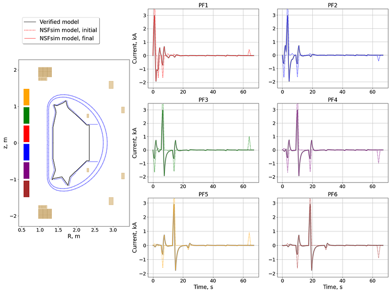
Step 1: Current dynamics under constant-voltage control. We first ensured that coil currents exhibited the correct dynamic response (Figure 1).

EAST is a fully superconducting tokamak, and therefore the resistance of its poloidal field (PF) coils is extremely low — on the order of several nano-ohms. In our initial replica, vacuum shot replays showed negligible current dissipation, inconsistent with the reference simulation (dotted traces in Figure 2). To reproduce the correct coil current behavior in NSFsim, it was necessary to evaluate the power supply circuit’s influence on current dissipation. The simplest way to do this in NSFsim is to include the power supply resistance in the coil’s effective resistance. Based on the information about coil and power supply properties published in [3, 4], we adjusted the coil resistances in our replica. Additionally, the resistances of the IC coils were adjusted based on [5]. The good agreement between coil currents and flux loop signals from the second set of vacuum shots and the reference data confirms the model’s validity.
Step 2: Magnetic-probe alignment. While flux loops then agreed, magnetic-probe signals still differed. This pattern points to probe geometry. After rechecking probe positions and orientations and correcting them in the model, NSFsim and CREATE results agreed within ~2% for flux loops and ~2.5% for magnetic probes (Figures 3 and 4).


Conclusion
Plasma-free verification with NSFsim proved essential for establishing a trustworthy electromagnetic baseline on EAST. Incorporating realistic power-supply resistance into the superconducting PF-coil effective resistances corrected the current-damping behavior, bringing coil currents and flux loop signals into agreement with the validated reference. Resolving magnetic-probe placement/orientation completed the alignment, yielding agreement at the 2–2.5% level across flux loops and probes. With passive structures and synthetic diagnostics validated in vacuum, the NSFsim replica is now suitable for subsequent studies that include plasma currents — such as transient control, VDE modeling, and halo-current assessment — where model/diagnostic consistency is critical.
Next Step Fusion is a supply chain company supporting tokamak developers in the design, simulation, optimization, control, and operation of their devices through integrated modeling and AI/ML-enabled solutions.
We invite you to be part of this groundbreaking journey!
At the moment, we’re very open to discussion and cooperation with specialists in fusion diagnostic systems!
Follow our blog on Medium, subscribe to our LinkedIn for regular updates, watch our videos on YouTube, or reach out to us directly to discuss potential collaborations.
References
- Clark, R., Nurgaliev, M., Khairutdinov, E., Subbotin, G., Welander, A., & Orlov, D. M. (2025). Validation of NSFsim as a Grad-Shafranov equilibrium solver at DIII-D. Fusion Engineering and Design, 211, 114765.
- Hu, J., Xi, W., Zhang, J., Huang, L., Yao, D., Zang, Q., … & EAST team. (2023). All superconducting tokamak: EAST. AAPPS bulletin, 33(1), 8.
- Fu, P., Liu, Z. Z., Gao, G., Yang, L., Song, Z. Q., Xu, L. W., … & Liu, X. N. (2010, June). Power supply system of EAST superconducting tokamak. In 2010 5th IEEE Conference on Industrial Electronics and Applications (pp. 457–462). IEEE.
- Weiyue, W., & Baozeng, L. (2003, October). Design of the PF system for EAST (HT-7U) tokamak. In 20th IEEE/NPSS Symposium on Fusion Engineering, 2003. (pp. 436–439). IEEE.
- Wang, X., Wang, Z., Xie, F., He, Q., Li, X., & Xie, W. (2019). Electromagnetic Analysis of the Updated Fast Control Coil for EAST. Manufacturing Technology, 19(1), 172–176.