Next Step Fusion Negative Triangularity Tokamak: Preliminary Design
As described in the previous article, we identified the key parameters of our medium-sized fusion machine, Negative Triangularity Tokamak (NTT), with an easily disassembled and water-cooling copper magnetic system. To implement the conceived technical solutions and achieve the required plasma parameters, we have started the preliminary design of our tokamak, the results of which are presented in this article.
POPCON Analysis
After we have decided on the device size range, we selected the smallest configuration capable of achieving a mega-ampere-scale plasma current while ensuring the target magnetic field of 3 Tesla could be sustained for 10 seconds. These constraints guided our selection of a tokamak’s geometric parameters: major radius (R) of 1 meter and an aspect ratio (A) of 3.75. Based on geometry, we chose a plasma current (Ip) of 0.75 MA to ensure the safety factor at the plasma boundary (q95) remains above the critical threshold of 3.
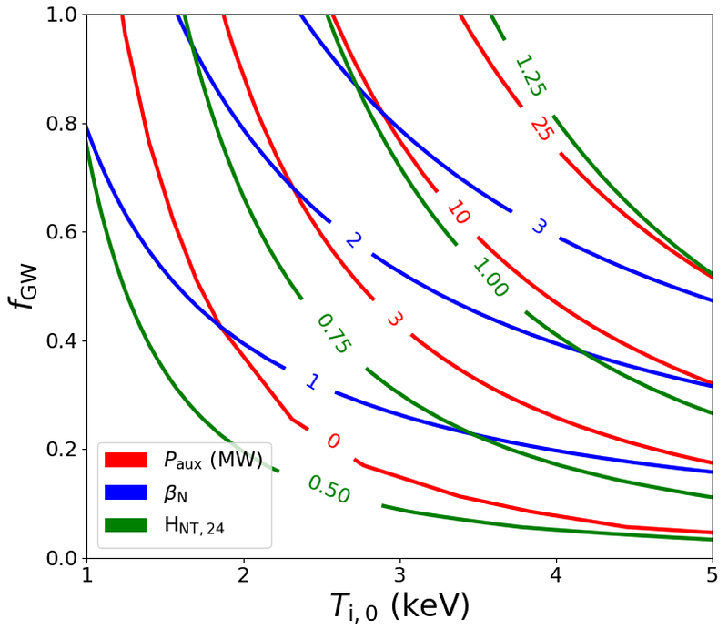
Using the NTT’s key parameters, we conducted a comprehensive analysis of its operational space using POPCON (Plasma OPerational CONtour). The results provide a detailed understanding of the NTT’s capabilities (Fig. 1):
- Ohmic plasma heating alone achieves central ion temperatures of Ti(0) = 2.5 keV at a Greenwald fraction fGW = 0.2.
- With 3 MW of auxiliary heating, temperatures rise to Ti(0) = 3 keV while maintaining fGW = 0.45.
Poloidal Magnetic System Configuration
Using simulation code TokaMaker, together with the Columbia Plasma Physics Lab, we’ve explored multiple magnetic configurations to design the NTT’s magnetic system. The process unfolded in six key stages (Fig. 2a–2f):
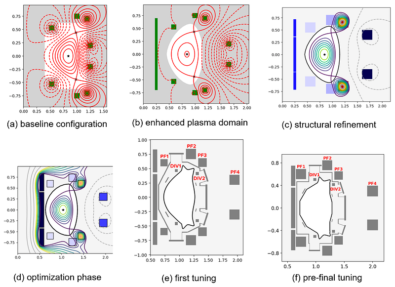
- Baseline configuration: A simplified setup with an approximate plasma boundary and poloidal fields (PF) coils only (Fig. 2a).
- Enhanced plasma domain: Introduced a solid central solenoid (CS) and sharper plasma boundary (Fig. 2b).
- Structural refinement: Added a generic vacuum vessel (VV) matching the plasma shape and segmented CS into three sections (Fig. 2c). Initial PF coil dimensions were derived from coil current estimates.
- Optimization phase: The positions and cross-sections of the PF coils were refined iteratively for improved performance, based on the plasma equilibria and PF current scenarios achieved during the design process. The final set consists of four couples of Upper/Lower symmetric PF coils and three CS sections (Fig. 2d).
- Final evaluation: Tested two realistic VV designs and limiter estimation (Fig. 2e and 2f). We optimized the VV’s geometry using NSFsim (as detailed in our earlier work).
Ultimately, we selected one of the configurations (Fig. 3), which served as the basis for a more detailed design of the NTT magnetic and other systems.

Engineering of the Magnet System
The NTT magnet system comprises a precisely engineered, minimum required and sufficient set of coils, each of which is essential for effective plasma confinement and stability over the plasma’s current, shape, and position control. We have optimized these coils for both manufacturability and power efficiency, resulting in a design that is both practical and high-performing, while still allowing for a wide range of plasma geometries. The final configuration of the PF coils is shown in Fig. 4. The proposed design utilizes eight PF coils with maximum currents of 2 MA to achieve a wide range of plasma geometries with −0.7 < δ < −0.3 and 1.5 < 𝜿 < 1.9.

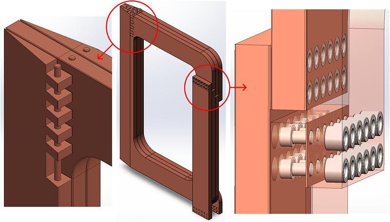
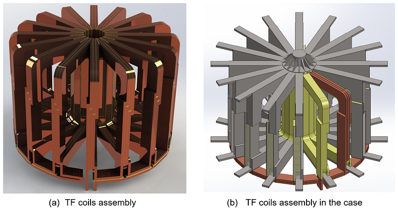
We initially determined that the toroidal field (TF) coils in our tokamak should be collapsible and constructed from water-cooled copper. Each coil consists of three turns, which can be manufactured by milling a single copper sheet into just two parts connected by stainless steel pins and bolts (Fig. 5). Most of each turn is formed from a single conductor with a cross-section of 56 × 270 mm, providing excellent mechanical durability.
A total of sixteen such coils are assembled into a single magnetic system using intermediate copper jumpers, along with the reverse turn for jumper’s current compensation (Fig. 6a). The inner sections of the coils are combined into a single central column, where the highest mechanical stresses occur. After assembly, the TF coil system is lined with an insulator and enclosed in a collapsible metal case, which ensures the mechanical integrity of the entire structure (Fig. 6b). We designed the assembly process to be feasible without requiring specialized equipment.
Inside the TF system, the vacuum vessel, CS, and PF1–3 coils are located. The PF4 coils are positioned outside the TF system. The wires in the PF coils are flat conductors twisted into an Archimedes spiral, as shown in Fig. 7a. This design achieves a higher coil filling factor (~0,9) compared to a standard conductor with an internal cooling channel.
The PF coils are cooled by distilled water at a pressure of 5 atmospheres, circulating through a single thin channel (Fig. 7b). Thermal calculations confirm that this method cools all coils back to their initial temperature within 15 minutes between pulses.

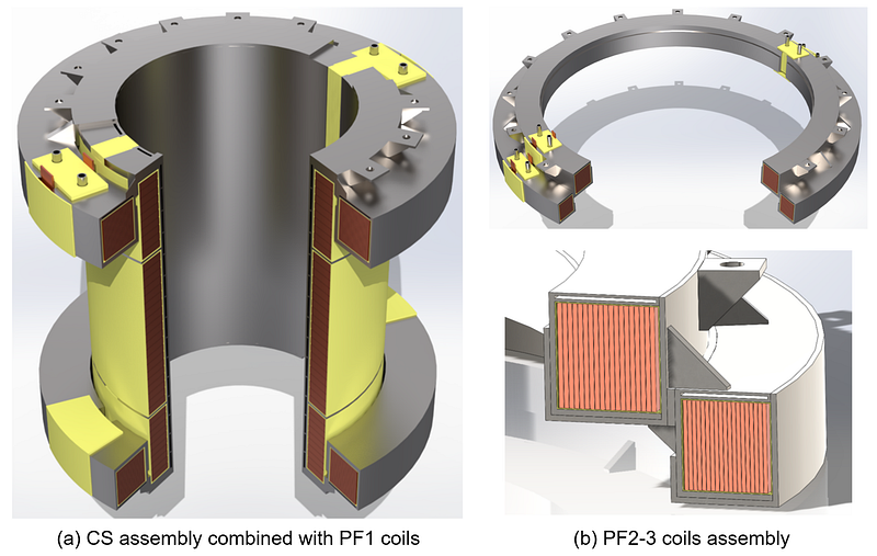
The CS is assembled from three sections, together with the PF1U/L coils (Fig. 8a), and is mounted on the lower parts of the disassembled TF coils through insolation. The PF2 and PF3 coils are assembled into a single frame (Fig. 8b) to provide resistance to magnetic forces of up to 5 T between the coils. Each coil has its water-cooling channels and is housed in a collapsible casing for easier maintenance.
Power Supply: A Critical Component
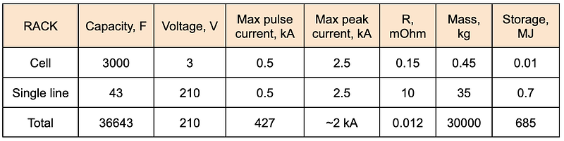
The NTT’s magnetic system power supply — a critical and costly component — uses supercapacitor-based energy storage to mitigate grid limitations. Key considerations include ensuring storage-load alignment despite gradual voltage decay during operation, which is maintained for inductive-resistive loads until the supply voltage matches the active resistance drop. The maximum current per cell depends on capacity and discharge time (pulse duration). Using magnetic system parameters (coil length, cross-section) and discharge scenarios, we evaluated core storage characteristics. Table 1 summarizes the toroidal system’s storage parameters.
We propose developing fully autonomous power supply modules that can be unified at the load current collector later. Each module, housed in a separate cubicle, contains all necessary components: capacitor charger and bank, IGBT H-bridge, LC filter, power switches, and self-diagnostics systems. This autonomy streamlines the assembly process.
A centralized control system synchronizes all modules, integrating with the Plasma Control System (PCS) and other critical systems (Synchronization, Interlock, and Network) as shown in Fig. 9.

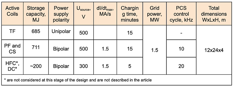
The basic parameters of the power supplies developed at this design stage are presented in Table 2.
Vacuum Vessel
During the preliminary stage, we evaluated two vacuum vessel (VV) designs: a cone-shaped (Fig. 10a) and a rectangular (Fig. 10b) configuration.
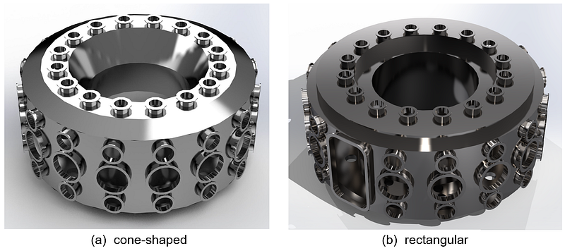
Our analysis revealed critical trade-offs:
- Cone-shaped VV:
(-) Conflict with magnetic coil placement
(-) Insufficient space for the first wall and divertor
(-) Compromised plasma volume requirements
(+) Provides better passive stabilisation due to closeness to plasma - Rectangular VV:
(+) No conflict with the coils, and also provides them with force support
(+) Increased internal space for plasma-facing components
(+) Simplified installation of in-vessel systems, and does not compromise plasma volume
(-) Provides poor passive stabilisation
While the rectangular configuration initially appeared optimal due to these geometric advantages, NSFsim simulations exposed a critical flaw: it provides weaker passive stabilization of plasma vertical displacement events — a safety hazard in tokamaks. Therefore, for the final selection of the VV configuration, we must optimize the machine, taking into account the passive stabilization coils, and further tune all resistive structures.
Support Structure
Designing the support structure for the NTT requires a careful balance between strength, size, and manufacturability. At the core of our design (Fig. 11) are two sturdy square frames, each measuring 300 mm on a side and 50 mm thick. These squares are reinforced with diagonal elements, creating a strong, stable base much like the cross-bracing found in modern architecture. Connecting these squares are eight robust crossbars, each with a diameter of 200 mm. This network of crossbars helps distribute mechanical loads evenly throughout the structure.
The structure features a smooth expansion toward the mounting points, which helps minimize stress concentrations and ensures a secure connection to the rest of the tokamak. Special grooves are also incorporated to provide a stable ledge for the TF coils, ensuring they remain securely in place during operation.
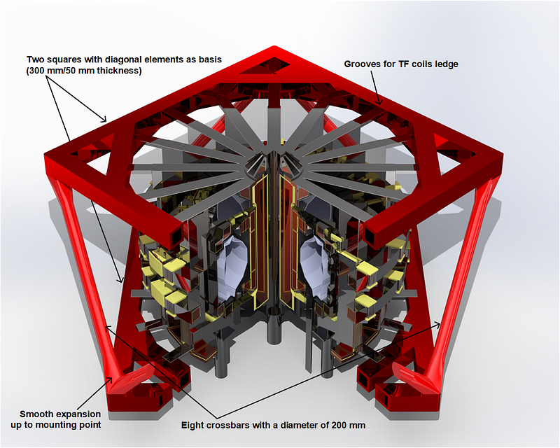
To ensure the structure can withstand the demanding conditions inside the NTT, we performed preliminary calculations and simulations to verify its strength and reliability. We tested the design by fixing a single TF coil at one end of the shell and applying external loads to simulate operational stresses. The results showed that the structure, when externally supported, could effectively handle these loads, maintaining its integrity and protecting the sensitive components inside.
Scenario Modelling (NSFsim)
Using our state-of-the-art plasma simulator NSFsim [2], we have developed several NTT discharge scenarios, one of which is shown in Fig. 12. The simulation confirmed that with the specified current limits in the coils, the desired plasma parameters are possible to obtain.
The digital replica of the NTT is available on the Fusion Twin Platform, which empowers researchers and fusion enthusiasts to model plasma behavior in various tokamak configurations using our advanced NSFsim tool. We invite you to experience the platform firsthand and model the NTT’s plasma behavior yourself.
Conclusion
Through our work, we’ve developed a robust design of the magnetic confinement fusion experimental machine, advancing the pursuit of fusion energy. Our collapsible, modular tokamak enables rapid restoration after the destruction associated with disruptive modes of plasma discharges.
If you are interested in developing and building a tokamak for any purpose, please contact us for advice and assistance. Our team of physicists and engineers has the necessary experience and competencies to support this task.
While this article omits detailed force stress and thermal load calculations (due to length constraints), these topics will be explored in a future publication. Stay tuned as we refine this design and progress toward our scientific and engineering objectives.
Next Step Fusion is a supply chain company supporting tokamak developers in the design, simulation, optimization, control, and operation of their devices through integrated modeling and AI/ML-enabled solutions.
We invite you to be part of this groundbreaking journey. Follow our blog on Medium, subscribe to our LinkedIn for regular updates, watch our videos on YouTube, or reach out to us directly to discuss potential collaborations.
References
[1] Electromagnetic System Conceptual Design for a Negative Triangularity Tokamak // arXiv:2501.14682. S. Guizzo, M.A. Drabinskiy, C. Hansen, A.G. Kachkin, E.N. Khairutdinov, A. O. Nelson, M.R. Nurgaliev, M. Pharr, G.F. Subbotin, C. Paz-Soldan.
[2] Validation of NSFsim as a Grad-Shafranov Equilibrium Solver at DIII-D // Fusion Engineering and Design V211, Feb. 2025. Randall Clark, Maxim Nurgaliev, Eduard Khayrutdinov, Georgy Subbotin, Anders Welander, Dmitri M. Orlov.