NSFSim Perspective on Disruptions in Tokamaks — Part I: Physics Basis
Part I: Physics Basis
Introduction
A plasma disruption is a rapid loss of magnetic confinement that ends the discharge (Fig. 1). In large and high magnetic field devices like tokamaks, this is a mission‑threatening if not mitigated: extreme thermal loads can melt plasma‑facing components, and electromagnetic forces can stress the vacuum vessel and other conducting structures, which can lead to their irreversible damage. Understanding the full disruption sequence — and simulating it end‑to‑end — is essential when designing new machines.
When we model disruptions, we must capture all phases: precursor evolution, thermal quench, current quench, rapid plasma motion, as well as related induced currents and halo currents in conductors. Each phase is associated with different damage channels and design margins. Models that do not include all major disruption phases may result in an underestimation of potential damage and, consequently, unplanned shutdowns later in operations.
Future fusion power plants, as well as currently operating large tokamaks, operate on the edge of robust, controllable regimes and require active control of disruptions. Various techniques have been developed to predict an approaching disruption [1], actively control plasma stability [2], and mitigate detrimental effects if a disruption is inevitable [3].

The anatomy of a disruption
Based on the underlying trigger and sequence of stages, two types of disruptions are usually distinguished: major disruption (MD) and hot Vertical Displacement Event (VDE) [5] (Fig. 2). Both bring different types of risks to tokamak operations such as thermal loads on the first wall, eddy and halo currents, runaway electrons (marked as red in Fig. 2).
The two most significant threats to the device during MD are:
- Eddy currents in conducting structures, which lead to high electromagnetic stresses [3],
- High fraction of runaway electrons, which can melt the plasma-facing components.
In case of hot VDE, the biggest threats to the device are:
- High thermal loads on the first wall,
- Electromagnetic forces due to halo currents.
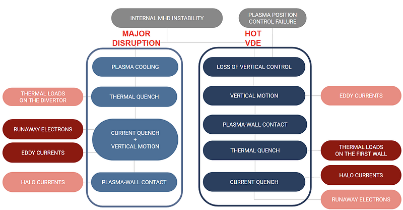
The classic major disruption unfolds in two distinct stages:
1) First comes a thermal quench, which is followed by a current quench, where the toroidal current decays over a much longer time. The plasma column becomes cold and highly resistive when the current starts to collapse; therefore, runaway electron generation is one of the dominant concerns in a major disruption.
2) Second comes current quench and simultaneous plasma movement. The current quench accelerates the vertical instability of the plasma [6], making it almost impossible to control. This results in eddy currents in the vacuum vessel and surrounding conducting structures, leading to extreme electromagnetic loads.
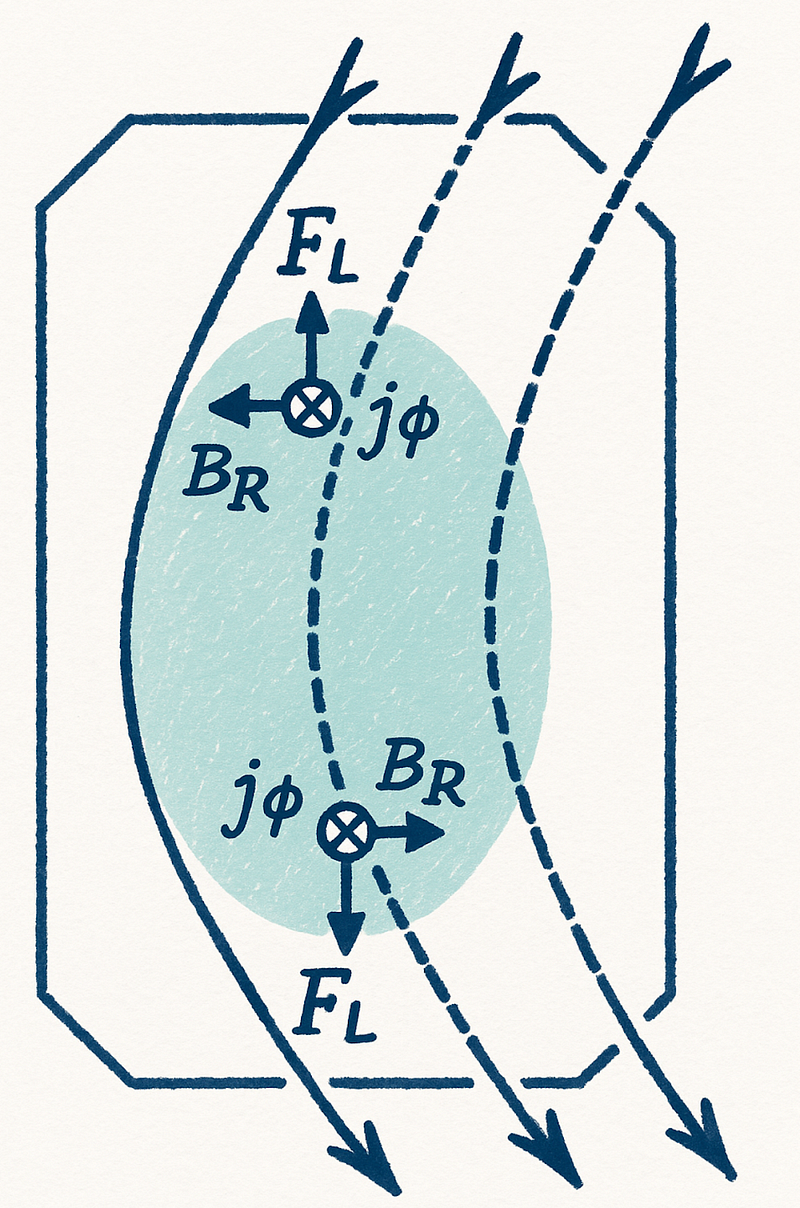
In case of the VDE, the vertical motion of the plasma column precedes both the thermal and current quenches. Elongated plasmas are intrinsically prone to this motion because the same poloidal‑field coils that shape the plasma carry co‑Iₚ currents that pull the column toward the upper and lower regions of the vacuum vessel (Fig. 3). Even a slight upward or downward shift unbalances these forces. Hence, the displacement grows rather than self‑corrects. On timescales comparable to the vessel’s resistive wall time, eddy currents in surrounding conductors, together with dedicated vertical‑stabilisation coils, can still restore equilibrium. If that feedback reacts too slowly or saturates, the column drifts into the wall — the VDE occurs.
A major disruption starts with an internal MHD instability that deteriorates confinement. The plasma cools, undergoes a thermal quench (TQ) (several ms at ITER), and then a much longer current quench (CQ) (hundreds of ms at ITER) during which the cold column can lose vertical stability and drift towards the wall. The TQ results in heat loads that are transferred via SOL to the divertor. The rapid plasma column motion induces eddy currents. CQ forms runaway‑electron beams. While halo currents are present, they are not dominant as the plasma-wall contact occurs only at a later stage of CQ.
The loss of vertical position control triggers hot VDE while the plasma is still hot. The column drifts, touches the wall, and only then cools in a TQ the subsequent CQ results in large halo currents and vertical/side forces. Here, the worst thermal loads land on the first wall. While eddy currents are still present, they pose a lower threat as CQ is longer compared to a major disruption.
How do disruptions start?
Disruptions can be set off by a wide range of events [8] — including an H-to-L-mode back‑transition, a giant ELM, or a hardware fault. Regardless of the trigger, the machine first enters a precursor phase: vertical or shape control failures, or an impurity influx breaches one of the machine’s operating limits, allowing large‑scale MHD activity to grow while the edge temperature collapses. The safe operating window of a tokamak is therefore bounded by the following stability limits [9]:
β limit — pressure ceiling
At a given toroidal magnetic field, the tokamak plasma can confine the kinetic pressure only up to a certain limit. This pressure limit can be defined using the β parameter. Fusion power increases roughly in proportion to the square of that pressure, so operating at high β is attractive. Yet when β grows beyond some threshold, pressure‑driven modes such as ballooning or peeling develop, and the discharge is lost.
Kruskal–Shafranov current limit — kink stability
Plasma current at a given toroidal magnetic field is limited due to the development of kink instability. The limit q(a) > 1 is necessary to avoid it, but it is not a sufficient condition; typically, q(a) > 2 is required for stable operation. In diverted plasma, routine operation keeps a comfortable margin typically q95 ≳ 3 to avoid resistive‑wall‑mode growth, although active feedback has demonstrated short pulses below this limit [10].
Density limit
Raising the line-averaged density can trigger a tearing mode due to the flattening of the current profile, while the core is still hot [11, 12]. Density increase boosts the fusion rate, but it can also increase edge radiation. Beyond a density known as the Greenwald limit, line radiation from partially ionised impurities cools the boundary faster than heating can replace the energy — the edge temperature crashes, triggering a disruption.
Disruptions phases
As we have seen above, each type of disruption includes the following phases in a different order: a precursor phase, a thermal quench, a current quench, and a plasma column displacement.
Precursor phase. Instabilities start to grow at the plasma edge (cooling there often kicks things off). To maintain a constant total toroidal current while conditions change, the current profile shifts, becoming sharper near the q = 2 surface and flatter in the center. This sets up big magnetic islands. As these islands grow and overlap, stochastization of magnetic field lines occurs, allowing heat to escape quickly across the field.
Thermal quench (TQ). Once the nested magnetic surfaces break up, electrons can stream freely; the effective cross‑field heat diffusivity increases, so energy leaves the core in a very short time. The heat loss often unfolds in two steps: core flattening (while edge surfaces can still provide some insulation) and edge barrier collapse (when 100% of the energy is delivered to the limiter/divertor or the first wall). While the current profile flattens in the center, internal inductance decreases. Assuming that magnetic flux is frozen into the wall on such a short timescale, Ip must momentarily rise to keep poloidal flux constant. This results in a typical negative loop voltage spike and a positive Ip spike, marking the transition from thermal quench to current quench [13].
Current quench (CQ). With the temperature drop, the plasma becomes more resistive, and the current drops as well. The transformer power supply can’t keep enough loop voltage, so the plasma current drops toward zero. The plasma usually drifts toward the wall during this stage. When large current loss and significant vertical motion happen together, this is often referred to as a major disruption.
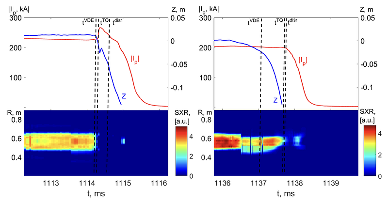
The difference between a major disruption and a hot VDE at the COMPASS tokamak is illustrated in Fig. 4. The major disruption exhibits a typical Ip spike followed by CQ with simultaneous vertical movement of the plasma column. The hot VDE starts with vertical displacement, and only when the plasma reaches the vacuum vessel wall the TQ begins. Therefore, almost full plasma current and full plasma energy are deposited on the vacuum vessel, resulting in more severe thermal loads.
Destructive impact of disruptions
Disruptions deliver thermal, runaway‑electron, and mechanical/electromagnetic loads. All scale strongly with machine size; what is routine on a small research tokamak can be life‑limiting on a bigger machine or a future fusion power plant.
Thermal Loads
During TQ, stored energy escapes through enhanced radiation and conduction along stochastic field lines. Large fractions can be deposited on a small surface area — divertor targets, first wall tiles, limiters — in milliseconds. Peak fluxes can surpass melting thresholds even for tungsten (Fig. 5). ITER‑class scenarios project ~350 MJ released if unmitigated; radiative mitigation is mandatory.

Runaway Electrons
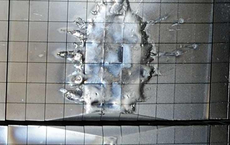
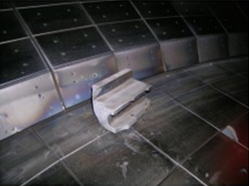
Strong electric fields inductively arising during CQ can accelerate a tail of electrons to relativistic energies (Dreicer, hot‑tail, and avalanche mechanisms). Concentrated runaway electron beams striking metal surfaces cause local melting, vaporization, thermal shock, micro‑cracking, and material phase changes — potentially punching through protective layers [15, 16] (Fig. 6).
Mechanical / Electromagnetic Loads
Changing magnetic fields and current paths induce large currents in conducting structures. Their interaction with background fields creates Lorentz forces that can deform structures, fatigue supports, and reduce component lifetime (Fig. 7).
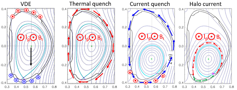
Each disruption phase can lead to a separate electromagnetic load channel due to the interaction of the currents in conducting structures and large magnetic fields. They may overlap in time, but we present them as a sequence for better understanding (Fig. 8). Vertical displacement of the plasma column changes the mutual inductance with surrounding conductors. It induces eddy currents in the vacuum vessel. These currents have a dipole-like structure and oppose the motion of the plasma. The thermal quench abruptly removes plasma diamagnetism, producing rapid changes in the toroidal field that induce poloidal eddy currents in the vessel. During the subsequent current quench, the fast decay of the plasma current changes both toroidal and poloidal magnetic fields; corresponding toroidal and poloidal eddy currents are induced within the vessel. Finally, once open field lines strike material surfaces, a fraction of the remaining plasma current diverts as halo currents that complete their circuit through the vessel and plasma-facing components; J×B with the toroidal field can impose large net vertical loads. Accurate load predictions require modeling all these current paths — and their overlaps — through the full 3‑D conductor set (vessel shells, supports, tiles, gaps, diagnostics). Missing a path can underpredict forces by large margins.
Disruption prediction and mitigation
Reliable disruption handling in tokamaks requires techniques from disruption prediction to their mitigation. Real‑time classifiers and survival‑analysis models process dozens of diagnostic signals to estimate a “time‑to‑disruption” with enough warning time for actuators [18]. Large, multi‑device benchmarks are aimed at standardising training data, helping machine‑learning predictors to become machine-agnostic and remain robust as operating regimes evolve.
Once an unavoidable disruption is flagged, “rapid shutdown” schemes such as massive gas injection or shattered‑pellet injection populate the plasma with high‑Z impurities [19]. The subsequent density rise radiates thermal energy isotropically, shortens current‑quench times, and suppresses runaway‑electron avalanches, alleviating mechanical and thermal loads.
Combining active stability control, data‑driven forecasting, and proven mitigation strategies is essential for future fusion power plants.
High‑fidelity disruption simulation is mandatory
The physics of disruptions defines the boundary conditions for tokamak design. Robust modelling is therefore a prerequisite, as it informs coil placement, wall thickness, diagnostic bandwidth, controller speed, and ultimately, the cost and availability of the plant.
Disruption simulations encompass a range of topics to reproduce the entire disruption sequence and its consequences reliably. 3D non‑linear MHD codes, such as JOREK [20, 21], M3D‑C1 [22], and NIMROD [23], resolve plasma instabilities that trigger thermal quenching. Electromagnetic and structural coupling tools like ANSYS [24] take the plasma‑induced voltages and currents from the free‑boundary codes and compute the resulting eddy, halo, and sideways forces in the vacuum vessel, blanket modules, and coils. Kinetic/fluid-kinetic tools, such as DREAM [25], provide self-consistent runaway-electron generation, transport, and wall impact, linking the electric-field history to material damage.
Axisymmetric free‑boundary solvers like DINA [26, 27, 28] allow fast simulations of the current‑quench, vertical motion, and halo‑current concerning realistic coil and wall geometries. DINA integrates the 2‑D Grad–Shafranov equilibrium with lumped‑circuit equations for coils and passive structures, simulating eddy‑current formation and plasma evolution with an implicit finite‑difference scheme. NSFsim utilizes a proven DINA physics core, coupled with transport equations. NSFsim can be used for various purposes, such as developing discharge scenarios, planning experiments, and training machine learning models for plasma control [29].
The second part of this series will demonstrate how NSFsim simulation tools are applied in disruption simulations and what they reveal for the Divertor Tokamak Test facility (DTT) [30].
Next Step Fusion is a supply chain company supporting tokamak developers in the design, simulation, optimization, control, and operation of their devices through integrated modeling and AI/ML-enabled solutions.
We invite you to be part of this groundbreaking journey!
Follow our blog on Medium, subscribe to our LinkedIn for regular updates, watch our videos on YouTube, or reach out to us directly to discuss potential collaborations.
References
[1] P.C. de Vries et al. Scaling of the MHD perturbation amplitude required to trigger a disruption and predictions for ITER
[2] K Erik J Olofsson et al, General Atomics, Fast calculation of the tokamak vertical instability
[3] M. Lehnen et al., Disruptions in ITER and strategies for their control and mitigation
[4] R. Granetz, Disruption research on Alcator C-Mod
[5] G. Pautasso et al, The ITER disruption mitigation trigger: developing its preliminary design
[6] Y Nakamura et al, Mechanism of vertical displacement events in JT-60U disruptive discharges
[7] EPFL course PHYS-748: Control and Operation of Tokamaks
[8] P.C. de Vries et al, Survey of disruption causes at JET
[9] Hartmut Zohm, Magnetohydrodynamic Stability of Tokamaks
[10] P. Piovesan et al, Tokamak Operation with Safety Factor q95 < 2 via Control of MHD Stability
[11] M. Greenwald et al, A new look at density limits in tokamaks
[12] F. Salzedas et al, Secondary instability as cause of minor disruptions in density limit tokamak plasmas Available to Purchase
[13] E. Nardon, On the origin of the plasma current spike during a tokamak disruption and its relation with magnetic stochasticity
[14] E. Matveeva, Current quench and vessel currents characterisation at the COMPASS tokamak
[15] I. Jepu et al, Beryllium melting and erosion on the upper dump plates in JET during three ITER-like wall campaigns
[16] G. F. Matthews, Melt damage to the JET ITER-like Wall and divertor
[17] E. Matveeva, Studies of plasma disruptions in the COMPASS tokamak, PhD thesis, Charles University, Prague 2022
[18] R.A. Tinguely et al, An application of survival analysis to disruption prediction via Random Forests
[19] S. Jachmich et al, Shattered Pellet Injection experiments at JET in support of the ITER Disruption Mitigation System design
[20] JOREK website
[21] F.J. Artola. Free-boundary simulations of MHD plasma instabilities in tokamaks. PhD thesis, Aix-Marseille University, Marseille, 2018
[22] M3D‑C1 website
[23] NIMROD website
[24] R. Lombroni et al, Using MAXFEA code in combination with ANSYS APDL for the simulation of plasma disruption events on EU DEMO
[25] M. Hoppe et al, DREAM: a fluid-kinetic framework for tokamak disruption runaway electron simulations
[26] Lei Xue et al, Simulation of Plasma Disruptions for HL-2M with the DINA Code
[27] V. Lukash et al, Validation of halo current model with DINA code against JT-60U disruption shots
[28] J-Y Favez et al, Comparing TCV experimental VDE responses with DINA code simulations
[29] R. Clark et al, Validation of NSFsim as a Grad-Shafranov equilibrium solver at DIII-D
[30] DTT website